Search filter
Filter
Reset- Installation drawing (796)
- Product data sheet (751)
- Installation instructions (281)
- 3D model (144)
- Tender texts (127)
- Product scale drawing (104)
- Certificate (94)
- Declarations of performance (70)
- Cable plan (65)
- Declaration of conformity (63)
- Environmental declaration (48)
- Wiring diagram (42)
- User manual (29)
- Supplementary sheet (24)
- Product brochure (19)
- Flyer/folder (18)
- Type examination certificate (7)
- Inspection certificate (7)
- T&C / Data Protection (5)
- Supplier information (4)
- Product shot (2)
- Safety analysis (2)
- Software (2)
- Customer information (2)
- Evaluation/comment (1)
2707 results found
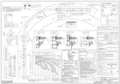
Installation drawing OL 90 N flexible link arm for round and segmental arch window
(PDF | 435 KB)
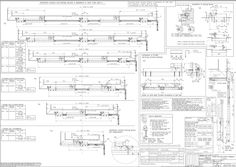
Installation plan OL 90 N top hung outward with locking device
(PDF | 491 KB)
Technical data and installation instructions rain / wind control unit with weather station P 03
Regen- / WindSteuerung mit Wetterstation P03 Rain/wind control with weather station P03 139860-02 DE Technische Daten und Installationshinweise GB Technical data and installation instructions Wetterstation P03 / Weather station P03 Inhaltsverzeichnis Symbole und Darstellungsmittel / Symbols and means of representation … Produkthaftung / Product liability … 2 … Lieferumfang / Scope of delivery … 2 Produktbeschreibung / Product description … Aufbau der Platine / Circuit board design … 3 Montage / Mounting … Standort / Location … Montage des Halters / Mounting the retainer … Montage der Wetterstation / Mounting the weather station … Montage des Steuergeräts / Mounting the control device … 4 Inbetriebnahme / Commissioning … 5 Betrieb / Operation … 6 Wartung / Maintenance … 11 … Technische Daten Wetterstation / Weather station technical data … 12 … Abmessungen / Dimensions … 13 Wetterstation P03 / Weather station P03 Symbole und Darstellungsmittel / Symbols and means of representation Warnhinweise / Warnings In dieser Anleitung werden Warnhinweise verwendet, um Sie vor Sach- und Personenschäden zu warnen. XX Lesen und beachten Sie diese Warnhinweise immer. XX Befolgen Sie alle Maßnahmen, die mit dem Warnsymbol und Warnwort gekennzeichnet sind. In these instructions, warnings are used to warn against material damage and injuries. XX Always read and observe these warnings. XX Observe all the measures that are marked with the warning symbol and warning word. Warnsymbol / Warnwort / Bedeutung / Meaning Warning Warning word symbol Gefahren für Personen. WARNUNG Nichtbeachtung kann zu Tod oder schweren Verletzungen führen. warning – VORSICHT CAUTION Danger for persons. Non-compliance can result in death or serious injuries. Informationen zur Vermeidung von Sachschäden, zum Verständnis oder zum Optimieren der Arbeitsabläufe. Information on avoiding material damage, understanding a concept or optimising the processes. Weitere Symbole und Darstellungsmittel / Further symbols and means of representation Um die korrekte Bedienung zu verdeutlichen, sind wichtige Informationen und technische Hinweise besonders herausgestellt. Important information and technical notes are emphasised in order to illustrate the correct operation. Symbol Bedeutung / Meaning bedeutet „Wichtiger Hinweis“ means “important note” bedeutet „Zusätzliche Information“ means “additional information” XX Symbol für eine Handlung: Hier müssen Sie etwas tun. XX Halten Sie bei mehreren Handlungsschritten die Reihenfolge ein. Symbol for an action: Here you have to do something. XX Observe the sequence if there are several action steps. Produkthaftung / Product liability Gemäß der im Produkthaftungsgesetz definierten Haftung des Herstellers für seine Produkte sind die in dieser Broschüre enthaltenen Informationen (Produktinformationen und bestimmungsgemäße Verwendung, Fehlgebrauch, Produktleistung, Produktwartung, Informations- und Instruktionspflichten) zu beachten. Die Nichtbeachtung entbindet den Hersteller von seiner Haftungspflicht. Für Änderungen der Normen und Standards nach Erscheinen der Installationsanleitung ist GEZE nicht haftbar. In accordance with the liability of manufacturers for their products as defined in the German “Produkthaftungsgesetz” (Product Liability Act), the information contained in these instructions (product information and proper use, misuse, product performance, product maintenance, obligations to provide information and instructions) is to be observed. Non-compliance releases the manufacturer from its statutory liability. GEZE is not liable for changes to the norms and standards after the installation instructions have been published. … Lieferumfang / Scope of delivery … Wetterstation P03 / Weather station P03 Lieferumfang / Scope of delivery Die Regen-/Wind-Steuerung (Mat.Nr. 91529) besteht aus folgenden Komponenten: àà Steuergeräte Regen/Wind àà Wetterstation P03 (Mat. Nr. 139579) Optional erhältlich: àà Anzeigemodul mit zwei LEDs (Mat.Nr. 29238) The rain/wind control unit (Mat. No. 91529) consists of the following components: àà Rain/wind control devices àà Weather station P03 (Mat. No. 139579) Optionally available: àà Display module with two LEDs (Mat. No. 29238) … Produktbeschreibung / Product description Die Wetterstation P03 misst Temperatur und Windgeschwindigkeit und erkennt Niederschläge. Die P03 gehört zum Lieferumfang der Regen-/Wind-Steuerung. The weather station P03 measures the temperature and wind speed and recognises precipitation. The P03 belongs to the scope of delivery of the rain/wind control unit. … Aufbau der Platine / Circuit board design … 1 … 3 Montage / Mounting … Standort / Location … Steckplatz für Anschluss der Steuerung / Slot for connecting the control unit 1: +24 V DC 2: GND 3: Daten / Data Steckplatz für Kabelverbindung zum Niederschlags sensor im Gehäusedeckel / Slot for cable connection to the precipitation sensor in the housing cover Wählen Sie eine Montageposition am Gebäude, wo Wind, Regen und Sonne ungehindert von den Sensoren erfasst werden können. Es dürfen keine Konstruktionsteile über der Wetterstation angebracht sein, von denen noch Wasser auf den Niederschlagssensor tropfen kann, nachdem es bereits aufgehört hat zu regnen oder zu schneien. Die Wetterstation darf nicht durch den Baukörper oder zum Beispiel Bäume abgeschattet werden. Unter der Wetterstation muss mindestens 60 cm Freiraum belassen werden, um eine korrekte Windmessung zu ermöglichen und bei Schneefall ein Einschneien zu verhindern. Select a mounting position on the building where wind, rain and sun can be detected unhindered by the sensors. There may not be any constructional parts over the weather station from which water can still drop onto the precipitation censor after it has already stopped raining or snowing. Shadows, for example from the building or trees, may not fall onto the weather station. There has to be at least 60 cm clearance under the weather station in order to enable correct wind measurement and, in case of snow fall, to prevent it being snowed over. … Wetterstation P03 / Weather station P03 Montage / Mounting àà Die Wetterstation muss an einer senkrechten Wand (bzw. einem Mast) (1) angebracht werden. àà The weather station has to be mounted on a vertical wall (or a mast) (1). … àà Die Wetterstation muss in der Querrichtung horizontal (waagrecht) (2) montiert sein. … àà In the cross direction the weather station has to be mounted horizontally (2). … Montage des Halters / Mounting the retainer Die Wetterstation beinhaltet einen kombinierten Wand-/Masthalter. Der Halter ist bei Lieferung mit Klebestreifen an der Gehäuserückseite befestigt. The weather station contains a combined wall/mast retainer. On delivery the retainer is fastened to the housing rear by means of adhesive strips. XX XX XX XX Halter senkrecht an Wand oder Mast befestigen. Bei Wandmontage: ebene Seite zur Wand, halbmondförmiger Steg (1) nach oben. … Fasten the retainer vertically to the wall or mast. For wall-mounting: flat side to the wall, crescentshaped bar (1) upwards. XX Bei Mastmontage: geschwungene Seite zum Mast, Steg (1) nach unten. XX For mast mounting: curved side to the mast, bar (1) downwards. … 5 Montage / Mounting Wetterstation P03 / Weather station P03 … Montage der Wetterstation / Mounting the weather station … .1 Allgemeine Hinweise / General information Öffnen Sie die Wetterstation P03 nicht, wenn Wasser (Regen) eindringen kann: Schon wenige Tropfen könnten die Elektronik beschädigen. Do not open the weather station P03 if water (rain) can ingress: Even just a few drops can damage the electronics. Bei der Montage ist darauf zu achten, dass der Temperatursensor (kleine Platine an der Unterseite des Gehäuses) nicht beschädigt wird. Auch die Kabelverbindung zwischen Platine und Regensensor darf beim Anschluss nicht abgerissen oder geknickt werden. Ensure during mounting that the temperature sensor (small circuit board at the lower part of the housing) is not damaged. Also ensure that the cable connection between the circuit board and the rain sensor is not ripped off or bent. … .2 Vorbereitung der Wetterstation / Preparing the weather station … 2 … 4 … 2 … 4 Deckel mit Regensensor / Cover with rain sensor Rasten des Deckels / Latches of the cover Platine / Circuit board Gehäuse-Unterteil / Housing lower part Der Deckel der Wetterstation mit dem Regensensor ist am unteren Rand rechts und links eingerastet. XX Deckel von der Wetterstation abnehmen. Vorsicht! Sachschaden! XX Sorgfältig vorgehen, um die Kabelverbindung zwischen der Platine im Unterteil und dem Regensensor im Deckel nicht abzureißen (Kabel mit Stecker). XX XX Kabel für die Spannungsversorgung und Busanschluss durch die Gummidichtung an der Unterseite der Wetterstation führen. Spannung und Bus an die dafür vorgesehenen Klemmen anschließen. Die Zuleitung zur Wetterstation darf maximal 30 m lang sein. Der Anschluss erfolgt mit handelsüblichem Telefonkabel (J-Y(ST)Y … × … × 0,8). The cover of the weather station with the rain sensor is latched in on the right and left of the lower edge. XX Remove the cover from the weather station. Caution! Material damage! XX Proceed carefully so that you do not rip off the cable connection between the circuit board in the lower part and the rain sensor in the cover (cable with plug). XX … Lay the cables for the voltage supply and the bus connection through the rubber seal at the lower part of the weather station. Wetterstation P03 / Weather station P03 XX Montage / Mounting Connect the voltage and bus to the corresponding terminals. The cable to the weather station may have a maximum length of 30 m. Connection is carried out with a common phone cable (J-Y(ST)Y … × … × … ). … .3 Anbringen der Wetterstation / Attaching the weather station Die Wetterstation muss so montiert werden, dass die Sensorfläche des Regenfühlers im Winkel von 45° nach unten weist. Regen und Wind müssen ungehindert auf das Gerät einwirken können. The weather station has to be mounted so that the sensor surface of the rain sensor forms an angle of 45° downwards. It must be possible for the rain and wind to act unimpaired on the unit. XX Deckel über das Unterteil stülpen. Der Deckel muss rechts und links mit einem eindeutigen „Klick“ einrasten. XX Prüfen, ob Deckel und Unterteil richtig eingerastet sind. Die Abbildung zeigt die geschlossene Wetterstation von unten mit der Raste (1). XX Put the cover onto the lower part. The cover has to latch in on the right and left with an audible “Click”. XX Check whether the cover and lower part are latched in correctly. The figure shows the closed weather station from below with the latch (1). … Gehäuse von oben in den montierten Halter schieben. Die Zapfen des Halters müssen dabei in den Schienen des Gehäuses einrasten. XX Slide the housing from above into the mounted retainer. The pins of the retainer have to latch into the rails of the housing. XX … Montage / Mounting … Wetterstation P03 / Weather station P03 Montage des Steuergeräts / Mounting the control device Die Leitungsverlegung und der Anschluss dürfen nur durch eine zugelassene Elektrofirma durchgeführt werden. àà Das Steuergerät darf nicht im Außenbereich montiert werden. àà Zweckmäßigerweise wird es in der Nähe der Wetterstation montiert. àà Die Leitungslänge darf max. 30 m betragen. Laying and connection of cables may only be carried out by an approved electrician. àà The control device may not be mounted outdoors. àà It makes sense to mount it near the weather station. àà The max. cable length amounts to 30 m. Kabelverlegung / Cable length … 2 x … x … mm … (max. 30 m) … 3x1.5 mm 230 V AC … 2 … x … x … mm … 2 … Wetterstation / Weather station Steuergerät / Control device … 3 … potentialfreie Schaltausgänge / Potential-free switching outputs Anzeigeeinheit / Display unit * bei 230 V – … x 1,5 mm2 / at 230 V – … x … mm2 * bei 24 V – … x … x 0,8 mm2 / at 24 V – … x … x … mm2 … Wetterstation P03 / Weather station P03 … Inbetriebnahme / Commissioning Inbetriebnahme / Commissioning WARNUNG! Lebensgefahr durch Stromschlag! XX Beim Anschluss der Wetterstation alle zu montierenden Leitungen spannungslos schalten (Netzsicherung des Steuergerätes ausschalten). XX Sicherheitsvorkehrungen gegen unbeabsichtigtes Einschalten treffen. Vorsicht! Zerstörung der Wetterstation oder mit ihr verbundene elektronische Geräte! XX Auf korrekten Anschluss achten. Nach dem Auspacken ist das Gerät unverzüglich auf eventuelle mechanische Beschädigungen zu untersuchen. Wenn ein Transportschaden vorliegt, ist unverzüglich der Lieferant davon in Kenntnis zu setzen. Die Wetterstation darf bei Beschädigung nicht in Betrieb genommen werden. XX Wenn anzunehmen ist, dass ein gefahrloser Betrieb nicht mehr gewährleistet ist, so ist die Anlage außer Betrieb zu nehmen und gegen unbeabsichtigten Betrieb zu sichern. Die Wetterstation darf nur als ortsfeste Installation betrieben werden, das heißt, nur in eingebautem Zustand und nach Abschluss aller Installations- und Inbetriebnahmearbeiten und nur im dafür vorgesehenen Umfeld. WARNING! Danger of fatal injury via electric shock! XX When connecting the weather station deenergize all the cables to be mounted (switch off the mains fuse of the control device). XX Take precautionary measures against unintentional activation. Caution! Destruction of the weather station or the electronic devices connected to it! XX Ensure proper connection. Inspect the device immediately after unpacking for any mechanical damage. If there is any transport damage, inform the supplier immediately. The weather station may not be put into operation if damaged. XX If it is to be assumed that safe operation is no longer possible, take the system out of operation and secure it against unintentional operation. The weather station may only be operated as a fixed installation, meaning only in the built-in state and after all the installation and commissioning work has been completed and only in the specified environment. … Betrieb / Operation Vorsicht! Sachschaden! Bei einsetzenden Regen, kann je nach Regenmenge und Außentemperatur eine gewisse Zeit vergehen, bis die Steuerung „Regenalarm“ erkennt. Es dürfen sich keinesfalls empfindliche Geräte, die durch ein „spät“ schließendes Fenster beschädigt werden könnten, in diesem Bereich befinden. Caution! Material damage! When it starts raining, it may take some time until the control unit recognises "Rain alarm", depending on the amount of time and the outdoor temperature. Under no circumstances may sensitive devices that could be damaged by a window closing too "late" be located in this area. … Betrieb / Operation Wetterstation P03 / Weather station P03 … 3 (a) (b) … 7 LED 17 … 1m/s 2m/s 4m/s 8m/s F1 … LED ON OFF … 8 13 14 15 … 16 … L1 N PE 3x1.5 mm … 14 … LEDs … W R + 230 V AC 50/60 Hz 12 … 5 … x … x … mm … W R 2x1.5 mm2 2x1.5 mm2 … x … x … mm … (max. 30 m) 10 … 11 … 3 … 2 (a) (b) … 4 … 6 … 8 10 Primärsicherung M 100 mA / Primary fuse M 100 mA Einstellung der Betriebsart mit Jumper / Setting of operating mode with jumper Relais getrennt / Separate relay operation Relais gemeinsam / Common relay operation Einstellung der Windgeschwindigkeit / Setting of the wind speed Kontroll-LED (blinkt, wenn Verbindung zur Wetter station OK ist) / Control LED (flashes if connection to weather station is OK) LED (Wind) / LED (wind) LED (Regen) / LED (rain) Windalarm / Wind alarm Signal … 10 11 12 13 14 15 16 17 Wetterstation / Weather station Anzeigemodul / Display module Wetterstation mit Regenfühler, Windfühler und Außen temperaturfühler / Weather station with rain sensor, wind sensor and outside temperature sensor potentailfreie Schließer max. … A / 230 V / Potential-free NO contacts max. … A / 230 V Steuergerät für Regen-/Windsteuerung / Control device for rain/wind control unit Netz / Power Relais Kontakt Wind / Relay contact wind Relais Kontakt Regen / Relay contact rain Trafo / Transformer Wetterstation P03 / Weather station P03 … .1 Wartung / Maintenance Einstellung der Windgeschwindigkeit / Setting of the wind speed Durch Addition der Werte können alle Kombinationen zwischen … m/s und 15 m/s eingestellt werden. (z.B. … m/s + … m/s = … m/s) All the combinations between … m/s and 15 m/s can be set by adding the values. (e.g. … m/s + … m/s = … m/s) … .2 Einstellung der Betriebsart mit Jumper / Setting of operating mode with jumper Relais getrennt: Regen- und Windalarm werden unabhängig geschaltet. Relais gemeinsam: Bei Regen- oder Windalarm werden stets beide Relais geschaltet (Standardeinstellung in Verbindung mit RWA-Zentrale). Separate relay operation: Rain and wind alarms are switched separately. Common relay operation: In case of a rain or wind alarm both relays are always switched together (default setting in combination with an RWA control unit). … Wartung / Maintenance Die Wetterstation und der Regenfühler sollten regelmäßig zweimal pro Jahr auf Verschmutzung überprüft und bei Bedarf gereinigt werden. Bei starker Verschmutzung kann der Windsensor funktionsunfähig werden oder ständig eine Regenmeldung anliegen. The weather station and the rain sensor should be checked regularly twice a year for soiling and if required cleaned. In case of strong soiling the wind sensor can become inoperative or a rain message be active constantly. 11 Technische Daten Wetterstation / Weather station technical data … Wetterstation P03 / Weather station P03 Technische Daten Wetterstation / Weather station technical data Beschreibung / Description Wert / Value Betriebsspannung / Operating voltage Strom / Current Montageart / Type of installation Datenausgabe / Data output Umgebungstemperatur / Ambient temperature Schutzklasse / Degree of protection Maße / Dimensions Gewicht / Weight 24 V DC max. 105 mA, Restwelligkeit 10% / Max. 105 mA, residual ripple 10% Aufputz / Surface mounting eigenes Datenprotokoll (WG-Bus) / Own data protocol (weather station bus) – 30 °C bis + 50 °C (Betrieb) / – 30 °C to + 50 °C (operation) – 30 °C bis + 70 °C (Lagerung) / – 30 °C to + 70 °C (storage) IP 44 ca. 96 mm x 77 mm x 118 mm (B x H x T) / Approx. 96 mm x 77 mm x 118 mm (W x H x D) ca. 148 g / Approx. 148 g Klemmbezeichung / Terminal designation Beschreibung / Description Wert / Value Wetterstation P03 / Weather station P03 1: +24 V DC 2: GND 3: Daten / Data Anzeigemodul mit zwei LEDs / DIsplay module with two LEDs Beschreibung / Description Wert / Value Maße / Dimensions 52 mm x 50 mm x 37 mm (B x H x T) / 52 mm x 50 mm x 37 mm (W x H x D) Regensensor / Rain sensor Beschreibung / Description Wert / Value Heizung / Heating ca. 1,2 Watt / Approx. … Watt Windsensor / Wind sensor Beschreibung / Description Wert / Value Messbereich / Measuring range Auflösung / Resolution Genauigkeit / Precision … m/s bis 15 m/s … m/s to 15 m/s < 10% des Messwerts / < 10% of the measured value ± 25% bei … ... 15 m/s bei Anströmwinkel 45°, Mastmontage / ± 25% at … ... 15 m/s at 45° flow angle, mast mounting Steuergerät / Control device 12 Beschreibung / Description Wert / Value Anschlussspannung / Supply voltage Schaltleistung / Switching capacity Messbereich / Measuring range Windgeschwindigkeit / Wind speed Verzögerungszeit / Delay time Schutzart / Protection type Maße / Dimensions 230 V AC 50/60 Hz … A / 230 V (2 Schließer) … A / 230 V (2 NO contacts) … m/s bis 15 m/s … m/s to 15 m/s ca. … Min. / Approx. … min IP 54 ca. 160 mm x 80 mm x 60 mm (B x H x T) Approx. 160 mm x 80 mm x 60 mm (W x H x D) Wetterstation P03 / Weather station P03 Technische Daten Wetterstation / Weather station technical data … Abmessungen / Dimensions … .1 Rückwand / Rear panel 14 22 71 35 … 75 Maße in mm. Bemaßung Gehäuserückseite mit Halter, technische Abweichungen möglich. Dimensions in mm. Dimensions of housing rear with retainer, technical deviations possible. … .2 Bohrplan / Drilling template Ø … mm … Langloch / Oblong hole 22 mm … x … mm 13 Technische Daten Wetterstation / Weather station technical data 14 Wetterstation P03 / Weather station P03 Wetterstation P03 / Weather station P03 Technische Daten Wetterstation / Weather station technical data 15 Germany GEZE Sonderkonstruktionen GmbH Planken … 97944 Boxberg-Schweigern Tel. +49 (0) 7930 9294 … Fax +49 (0) 7930 9294 10 E-Mail: sk.de@geze.com GEZE GmbH Niederlassung Süd-West Tel. +49 (0) 7152 203 594 E-Mail: leonberg.de@geze.com GEZE GmbH Niederlassung Süd-Ost Tel. +49 (0) 7152 203 6440 E-Mail: muenchen.de@geze.com GEZE GmbH Niederlassung Ost Tel. +49 (0) 7152 203 6840 E-Mail: berlin.de@geze.com GEZE GmbH Niederlassung Mitte/Luxemburg Tel. +49 (0) 7152 203 6888 E-Mail: frankfurt.de@geze.com GEZE GmbH Niederlassung West Tel. +49 (0) 7152 203 6770 E-Mail: essen.de@geze.com GEZE GmbH Niederlassung Nord Tel. +49 (0) 7152 203 6600 E-Mail: hamburg.de@geze.com GEZE Service GmbH Tel. +49 (0) 1802 923392 E-Mail: service-info.de@geze.com GEZE GmbH Reinhold-Vöster-Straße 21–29 71229 Leonberg Germany Austria GEZE Austria E-Mail: austria.at@geze.com www.geze.at Hungary GEZE Hungary Kft. E-Mail: office-hungary@geze.com www.geze.hu Scandinavia – Denmark GEZE Danmark E-Mail: danmark.se@geze.com www.geze.dk Baltic States GEZE GmbH Baltic States office E-Mail: office-latvia@geze.com www.geze.com Iberia GEZE Iberia S.R.L. E-Mail: info@geze.es www.geze.es Singapore GEZE (Asia Pacific) Pte, Ltd. E-Mail: gezesea@geze.com.sg www.geze.com Benelux GEZE Benelux B.V. E-Mail: benelux.nl@geze.com www.geze.be www.geze.nl India GEZE India Private Ltd. E-Mail: office-india@geze.com www.geze.in South Africa GEZE Distributors (Pty) Ltd. E-Mail: info@gezesa.co.za www.geze.co.za Italy GEZE Italia S.r.l E-Mail: italia.it@geze.com www.geze.it Switzerland GEZE Schweiz AG E-Mail: schweiz.ch@geze.com www.geze.ch GEZE Engineering Roma S.r.l E-Mail: roma@geze.biz www.geze.it Turkey GEZE Kapı ve Pencere Sistemleri E-Mail: office-turkey@geze.com www.geze.com Bulgaria GEZE Bulgaria - Trade E-Mail: office-bulgaria@geze.com www.geze.bg China GEZE Industries (Tianjin) Co., Ltd. E-Mail: chinasales@geze.com.cn www.geze.com.cn GEZE Industries (Tianjin) Co., Ltd. Branch Office Shanghai E-Mail: chinasales@geze.com.cn www.geze.com.cn GEZE Industries (Tianjin) Co., Ltd. Branch Office Guangzhou E-Mail: chinasales@geze.com.cn www.geze.com.cn GEZE Industries (Tianjin) Co., Ltd. Branch Office Beijing E-Mail: chinasales@geze.com.cn www.geze.com.cn France GEZE France S.A.R.L. E-Mail: france.fr@geze.com www.geze.fr Tel.: 0049 7152 203 … Fax.: 0049 7152 203 310 www.geze.com Poland GEZE Polska Sp.z o.o. E-Mail: geze.pl@geze.com www.geze.pl Romania GEZE Romania S.R.L. E-Mail: office-romania@geze.com www.geze.ro Russia OOO GEZE RUS E-Mail: office-russia@geze.com www.geze.ru Scandinavia – Sweden GEZE Scandinavia AB E-Mail: sverige.se@geze.com www.geze.se Scandinavia – Norway GEZE Scandinavia AB avd. Norge E-Mail: norge.se@geze.com www.geze.no Ukraine LLC GEZE Ukraine E-Mail: office-ukraine@geze.com www.geze.ua United Arab Emirates/GCC GEZE Middle East E-Mail: gezeme@geze.com www.geze.ae United Kingdom GEZE UK Ltd. E-Mail: info.uk@geze.com www.geze.com
(PDF | 1,017 KB)
Award certificate OL 90 fanlight openers with hand lever and scissor stay gripping and cleaning scissor stay
VERLEIHUNGS-URKUNDE AWARD CERTIFICATE Nr./ No. 13-4/99 (Version 03) Der Güteausschuss der Gütegemeinschaft Schlösser und Beschläge e.V. verleiht aufgrund des vorliegenden Prüfberichtes gemäß RAL-GZ 607/12 dem Oberlichtbeschlag: Based upon the test report according to RAL-GZ 607/12 which has been released by the quality assurance commission of the quality assurance association of locks and hardware hereby awards the fanlight hardware: OL 90 Oberlichtöffner mit Handhebel sowie der Fangschere FPS OL 90 Fanlight opener with hand lever and the safety shear FPS Fensterwerkstoff: Holz Window material: Wood Die Prüfergebnisse sind auf andere Fensterwerkstoffe übertragbar. The test results are transferable for other window materials der Firma: the company: GEZE GmbH Reinhold-Vöster-Str. 21-29 D-71229 Leonberg im Rahmen der Mitgliedschaft bei der Gütegemeinschaft Schlösser und Beschläge e.V., das von RAL (Deutsches Institut für Gütesicherung und Kennzeichnung e.V.) anerkannte Gütezeichen Schlösser und Beschläge mit der Inschrift „Oberlichtbeschläge“ as part of the membership of the Gütegemeinschaft Schlösser und Beschläge e.V., the RAL-quality label shown below, having been recognized by the German RAL Institute for Quality Assurance and labelling „Fanlight hardware” geprüft nach RAL-GZ 607/12, Ausgabe … certified according to RAL-GZ 607/12, version … Die Führung des Zeichens Nr. 13-4/99 setzt die Einhaltung und Überwachung nach dieser Güte- und Prüfbestimmung voraus. Grundlage ist der Prüfbericht Nr. 13-4/99, 13-4/ … und 13-4/ … des PIV. Permission of using this RAL quality label no. 13-4/99 is based on the surveillance and the quality- and testing instructions. The basis is test report no. 13-4/99, 13-4/ … and 13-4/ … by PIV. Diese Urkunde hat insgesamt … Seite und ersetzt die Urkunde 13-4/99 vom … .2017. This certificate has a total of … page and replaces the certificate 13-4/99 from … .2017. D-42551 Velbert, 10. Juli/ July 2024 Geschäftsführer Managing Director FB_07_13_02_20 Gütegemeinschaft Schlösser und Beschläge e.V. ∙ Offerstraße 12 ∙ D-42551 Velbert
(PDF | 351 KB)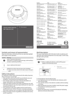
RM 1003 / 24 V DC optical smoke detector
Germany China GEZE Sonderkonstruktionen GmbH GEZE Industries (Tianjin) Co., Ltd. E-Mail: sk.de@geze.com E-Mail: Sales-info@geze.com.cn Russian OOO GEZE RUS E-Mail: office-russia@geze.com GEZE GmbH Niederlassung Nord-Ost E-Mail: berlin.de@geze.com GEZE Industries (Tianjin) Co., Ltd. Branch Office Shanghai E-Mail: chinasales@geze.com.cn GEZE GmbH Niederlassung West E-Mail: essen.de@geze.com GEZE Industries (Tianjin) Co., Ltd. Branch Office Guangzhou E-Mail: chinasales@geze.com.cn Scandinavia GEZE Scandinavia AB GEZE Sweden E-Mail: sverige.se@geze.com GEZE GmbH Niederlassung Mitte E-Mail: frankfurt.de@geze.com GEZE GmbH Niederlassung Süd-West E-Mail: leonberg.de@geze.com GEZE GmbH Niederlassung Süd-Ost GEZE Service GmbH NL Süd-West GEZE Service GmbH NL Nord-Ost GEZE Service GmbH NL West GEZE Service GmbH NL Mitte GEZE Service GmbH NL Süd Visual smoke detector RM 1003/24 V DC EN Wiring diagram Austria GEZE Austria GmbH E-Mail: austria.at@geze.com Baltic States GEZE GmbH Baltic States office E-Mail: office-latvia@geze.com Symbols and means of representation Important information and technical notes are especially highlighted to explain correct operation. Symbol Meaning means "Important Information"; Information on avoiding material damage, understanding a concept or optimising workflows. GEZE Scandinavia AB avd. Norge E-Mail: norge.se@geze.com GEZE Industries (Tianjin) Co., Ltd. Branch Office Beijing E-Mail: chinasales@geze.com.cn GEZE Finland E-Mail: finland.se@geze.com GEZE Denmark E-Mail: danmark.se@geze.com France GEZE France S.A.R.L. E-Mail: france.fr@geze.com Hungary GEZE Hungary Kft. E-Mail: office-hungary@geze.com Iberia GEZE Iberia S.R.L. E-Mail: info@geze.es Singapore GEZE (Asia Pacific) Pte. Ltd. E-Mail: gezesea@geze.com.sg South Africa DCLSA Distributors (Pty.) Ltd. E-Mail: info@gezesa.co.za Switzerland GEZE Schweiz AG E-Mail: schweiz.ch@geze.com India GEZE India Private Ltd. E-Mail: office-india@geze.com Turkey GEZE GmbH Türkiye - İstanbul E-Mail: office-turkey@geze.com Italy GEZE Italia S.r.l E-Mail: italia.it@geze.com Ukraine Repräsentanz GEZE Ukraine TOV E-Mail: office-ukraine@geze.com GEZE Engineering Roma S.r.l E-Mail: roma@geze.biz United Arab Emirates/GCC GEZE Middle East E-Mail: geze@emirates.net.ae Benelux GEZE Benelux B.V. E-Mail: benelux.nl@geze.com Poland GEZE Polska Sp.z o.o. E-Mail: geze.pl@geze.com Bulgaria GEZE Bulgaria - Trade E-Mail: office-bulgaria@geze.com Romania GEZE Romania S.R.L. E-Mail: office-romania@geze.com GEZE GmbH P.O.Box 1363 71229 Leonberg Germany Tel.: 0049 7152 203-0 Fax: 0049 7152 203-310 www.geze.com United Kingdom GEZE UK Ltd. E-Mail: info.uk@geze.com 153159-02 Brief description The visual smoke detector RM 1003 detects both smouldering and open fires with smoke development at an early stage. It works using the light scatter principle. Installation XX Before installing the detector, switch off the power supply to all monitoring circuits. means "additional information" … XX Symbol for an action: Here you have to do something. XX If there are several actions to be taken, keep to the given order. … Plastic tab (removal protection) Safety instructions It is important to follow these instructions for the safety of persons. These instructions must be kept. àà Only specialists authorised by GEZE are permitted to carry out installation, commissioning and maintenance work. àà Own changes made to the system will mean that GEZE is no longer responsible for any resulting damages. àà GEZE is not liable if products from other manufacturers are used with GEZE equipment. Use only original GEZE parts for repair and maintenance work as well. àà The connection to the mains supply must be carried out by a qualified electrician. Perform the power connection and equipment earth conductor test in accordance with VDE 0100 Part 610. àà Observe the latest versions of guidelines, standards and countryspecific regulations. XX XX XX XX XX XX Fit the detector into the detector base. Exert light pressure to turn the detector anti-clockwise until it slips into the holder. Turn until the notches in the detector correlate with the marking in the base. When all detectors have been installed, switch the power supply to the detector monitoring circuits on. Test detectors. Remove the plastic tab (1) to prevent the detector head being able to be removed without tools. Technical data Hold the test smoke under the detector. àà The red LED on the detector must change to a locked alarm state within 40 seconds. àà An alarm must be activated on the RWA control unit. XX Connection XX XX Remove the dust caps before commissioning the system. Heed wiring plan for the control unit. A maximum of 10 units or 20 units can be installed in series. (Depending on the control unit) … 2 Ø102 … Use a product from a recognised manufacturer to produce test smoke in accordance with the manufacturer's instructions. 42* Test * with base àà àà àà àà àà àà Functional principle Monitoring area Installation height Sensitivity Operating voltage Current consumption at 24 V DC àà idle àà during alarm àà Signal transmission àà Alarm reset àà Use … 4 + … 2 … 4 … 5 – First smoke detector Last smoke detector Insert the termination resistor in the last detector Terminal block GEZE emergency power control unit (see respective wiring diagram) Smoke detector connection àà Single indicator àà VdS approval àà Operating ambient temperature àà Dimensions with base àà Weight with base àà Colour visual light scatter principle according to application directives according to application directives DIN EN 54, Part … 8 V … 30 V DC max. 65 µA max. 20 mA 2-conductor technology current increase with self-locking by key in control unit only with GEZE emergency power control unit red LED G201060 -20 °C … +60 °C Ø 102 x 42 mm 120 g white, acc. to RAL 9016
(PDF | 371 KB)
E-drive E 212 R 230V
(PDF | 440 KB)
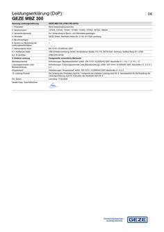
Declaration of performance (DoP): GEZE MBZ 300 SHEV control panel
Leistungserklärung (DoP): GEZE MBZ 300 DE Kennung Leistungserklärung GEZE MBZ 300_0786-CPD-50162 1. Produktart RWA Notstromsteuerzentrale 2. Identnummern 137428, 137430, 137461, 137463, 137462, 137453, 187322, 188034 3. Verwendungszweck Zur Verwendung in Rauch- und Wärmeabzugsanlagen 4. Hersteller GEZE GmbH, Reinhold-Vöster-Str. 21-29, D-71229 Leonberg 5. Bevollmächtigter ---- 6. System zur Bewertung der Leistungsbeständigkeit … 7. Harmonisierte Norm EN 12101-10:2005/AC:2007 … . Notifizierte Stelle VDS Schadenverhütung GmbH, Amsterdamer Straße 172-174, 50735 Köln, Germany, Notified Body ID = 0786 … . ID Zertifikat 0786-CPD-50162 9. Erklärte Leistung Festgestellte wesentliche Merkmale Betriebssicherheit Anforderungen "Betriebssicherheit" erfüllt - EN 12101-10:2005/AC:2007 Abschnitte … – … , 7, 9, … , 12 Leistungsparameter unter Brandeinwirkung Anforderungen "Leistungsparameter unter Brandeinwirkung" erfüllt - EN 12101-10:2005/AC:2007 Abschnitte … , … , … , … Ansprechzeit Anforderungen "Ansprechzeit" erfüllt - EN 12101-10:2005/AC:2007 Abschnitte … , … .2 10. Leistung Produkt Die Leistung des Produktes nach Nr. … entspricht der erklärten Leistung nach Nr. 9. Verantwortlich für die Erstellung der Leistungserklärung nach Nr. … ist allein der Hersteller nach Nr. 4. Ort, Datum Leonberg, … .2020 Gerald Haas, Geschäftsführer Declaration of Performance (DoP): GEZE MBZ 300 EN ID for Declaration of Performance GEZE MBZ 300_0786-CPD-50162 1. Type of product RWA emergency power control unit 2. Identity numbers 137428, 137430, 137461, 137463, 137462, 137453, 187322, 188034 3. Intended use For use in smoke and heat extraction systems 4. Manufacturer GEZE GmbH, Reinhold-Vöster-Str. 21-29, D-71229 Leonberg 5. Authorised person ---- 6. Assessment of constancy of performance … 7. Harmonised standard EN 12101-10:2005/AC:2007 … . Notified body VDS Schadenverhütung GmbH, Amsterdamer Straße 172-174, 50735 Köln, Germany, Notified Body ID = 0786 … . ID certificate 0786-CPD-50162 9. Declared performance Relevant characteristics determined Operational safety “Operational safety” requirements met - EN 12101-10:2005/AC:2007 sections … – … , 7, 9, … , and 12 Performance parameters under the effect of fire “Performance parameters under the effect of fire” requirements met - EN 12101-10:2005/AC:sections … , … , … , … Response time “Response time” requirements met - EN 12101-10:2005/AC:2007 sections … , … .2 10. Product performance The performance of the product according to No. … conforms to the declared performance according to No. 9. The manufacturer under No. … is solely responsible for preparing the declaration of performance according to No. 9. Place, date Leonberg, … .2020 Gerald Haas, Managing Director Déclaration des performances (DoP): GEZE MBZ 300 FR Identification Déclaration des performances GEZE MBZ 300_0786-CPD-50162 1. Type de produit Centrale de commande de secours RWA 2. Numéros d'identification 137428, 137430, 137461, 137463, 137462, 137453, 187322, 188034 3. Usage prévu Pour une utilisation dans les installations d’extraction de fumée et de chaleur 4. Fabricant GEZE GmbH, Reinhold-Vöster-Str. 21-29, D-71229 Leonberg 5. Mandataire ---- 6. Système pour l'évaluation des performances … 7. Norme harmonisée EN 12101-10:2005/AC:2007 … . Autorité notifiante VDS Schadenverhütung GmbH, Amsterdamer Straße 172-174, 50735 Köln, Germany, Notified Body ID = 0786 … . Certificat ID 0786-CPD-50162 9. Performances déclarées Principales caractéristiques constatées Sécurité de fonctionnement Exigences « Sécurité de fonctionnement » remplies - EN 12101-10:2005/AC:2007 sections … – … , 7, 9, … , et 12 Paramètres de performance sous l’effet d'un incendie Exigences « Paramètres de performance sous l’effet d’un incendie » remplies - EN 12101-10:2005/AC:2007 sections … , … , … , … Temps de réaction Exigences « Temps de réaction » remplies - EN 12101-10:2005/AC:2007 sections … , … .2 10. Performances du produit La performance du produit désignée sous n° … correspond à la performance déclarée sous n° 9. Le seul et unique responsable de l'établissement de la déclaration de performance selon n° … est le fabricant désigné sous n° 4. Lieu, date Leonberg, … .2020 Gerald Haas, Directeur Dichiarazione prestazioni (DoP): GEZE MBZ 300 IT Identificazione dichiarazione prestazioni GEZE MBZ 300_0786-CPD-50162 1. Tipo di prodotto Centralina di controllo corrente di emergenza RWA 2. Numeri ident. 137428, 137430, 137461, 137463, 137462, 137453, 187322, 188034 3. Impiego previsto Da utilizzare negli impianti di aspirazione fumo e calore 4. Produttore GEZE GmbH, Reinhold-Vöster-Str. 21-29, D-71229 Leonberg 5. Delegato ---- 6. Sistema per valutare la potenzialità … 7. Norma armonizzata EN 12101-10:2005/AC:2007 … . Ente notificato VDS Schadenverhütung GmbH, Amsterdamer Straße 172-174, 50735 Köln, Germany, Notified Body ID = 0786 … . Certificato ID 0786-CPD-50162 9. Prestazione dichiarata Caratteristiche importanti riscontrate Sicurezza di funzionamento Requisiti "Sicurezza di funzionamento " soddisfatti - EN 12101-10:2005/AC:2007 sezione … – … , 7, 9, … e 12 Parametri di rendimento sotto l'azione dell'incendio Requisiti "Parametri di rendimento sotto l'azione dell'incendio" - EN 12101-10:2005/AC:2007 sezioni … , … , … , … Tempo di reazione Requisiti "Tempo di reazione" soddisfatti - EN 12101-10:2005/AC:2007 sezioni … , … .2 10. Prestazione prodotto La prestazione del prodotto di cui al punto … corrisponde alla prestazione dichiarata nel punto 9. La responsabilità per la dichiarazione della prestazione di cui al punto … spetta soltanto al produttore di cui al punto 4. Località, data Leonberg, … .2020 Gerald Haas, Amministratore Delegato Declaración de rendimiento (DoP): GEZE MBZ 300 Identificación declaración de rendimiento GEZE MBZ 300_0786-CPD-50162 1. Tipo de producto Unidad de control de alimentación de emergencia RWA 2. Nº de identificación 137428, 137430, 137461, 137463, 137462, 137453, 187322, 188034 3. Finalidad Para el uso en sistemas de extracción de humos y calor 4. Fabricante GEZE GmbH, Reinhold-Vöster-Str. 21-29 D-71229 Leonberg 5. Mandatario ---- ES 6. Sistema para evaluar la resistencia de … rendimiento 7. Norma armonizada EN 12101-10:2005/AC:2007 … . Organismo notificado VDS Schadenverhütung GmbH, Amsterdamer Straße 172-174, 50735 Köln, Germany, Notified Body ID = 0786 … . Certificado ID 0786-CPD-50162 9. Rendimiento declarado Características principales constatadas Seguridad operativa Requisitos "Seguridad operativa" cumplidos- EN 12101-10:2005/AC:2007 Apartados … – … , 7, 9, … , y 12 Parámetros de rendimiento bajo exposición al fuego Requisitos "Parámetros de rendimiento bajo exposición al fuego" cumplidos - EN 12101-10:2005/AC:2007 Apartados … , … , … , … Tiempo de reacción Requisitos "Tiempo de reacción" cumplidos - EN 12101-10:2005/AC:2007 Apartados … , … .2 10. Rendimiento producto El rendimiento del producto según nº … se corresponde con el rendimiento declarado según nº … El fabricante es responsable exclusivo, según nº 9, de redactar la declaración de rendimiento conforme a nº … Lugar, fecha Leonberg, … .2020 Gerald Haas, director Toimintoselvitys (DoP): GEZE MBZ 300 Tunnistus toimintoselvitys GEZE MBZ 300_0786-CPD-50162 1. Tuotetyyppi RWA-varavoimaohjauskeskus 2. Tunnusnumerot 137428, 137430, 137461, 137463, 137462, 137453, 187322, 188034 3. Käyttötarkoitus Savun- ja lämmönpoistolaitteistot 4. Valmistaja GEZE GmbH, Reinhold-Vöster-Str. 21-29, D-71229 Leonberg 5. Valtuutettu ---- 6. Järjestelmä toimintojatkuvuuden arviointiin … 7. Sovellettu normi EN 12101-10:2005/AC:2007 … . Ilmoitettu paikka VDS Schadenverhütung GmbH, Amsterdamer Straße 172-174, 50735 Köln, Germany, Notified Body ID = 0786 … . ID-varmenne 0786-CPD-50162 9. Selvitetty toiminto Määritetyt olennaiset ominaisuudet Käyttöturvallisuus Vaatimukset ”Käyttöturvallisuus” täytetty – EN 12101-10:2005/AC:2007 luvut … – … , 7, 9, … , ja 12 Suorituskykyparametri tulelle altistumisessa Vaatimukset ”Suorituskykyparametri tulelle altistumisessa” täytetty – EN 12101-10:2005/AC: luvut … , … , … , … Vasteaika Vaatimukset ”Vasteaika” täytetty – EN 12101-10:2005/AC:2007 luvut … , … .2 10. Tuotteen suorituskyky Tuotteen suorituskyky numeron … mukaan vastaa numerossa … selvitettyä toimintoa. Valmistaja numeron … mukaan on yksin vastuussa numeron … mukaan laaditusta toimintoselvityksestä. Paikka, päivämäärä Leonberg, … .2020 Gerald Haas, toimitusjohtaja FI Δήλωση ισχύος (DoP): GEZE MBZ 300 EL Ειδικός αριθμός Δήλωσης απόδοσης GEZE MBZ 300_0786-CPD-50162 1. Τύπος προϊόντος Κέντρο ελέγχου ρεύματος ανάγκης RWA 2.Αριθμοί αναγνώρισης 137428, 137430, 137461, 137463, 137462, 137453, 187322, 188034 3. Σκοπός χρήσης Για τη χρήση σε συστήματα εξαερισμού για την απαγωγή καπνού και θερμότητας 4. Κατασκευαστής GEZE GmbH, Reinhold-Vöster-Str. 21-29, D-71229 Leonberg 5. Πληρεξούσιος ---- 6. Σύστημα για την αξιολόγηση της σταθερότητας απόδοσης … 7. Εναρμονισμένο πρότυπο EN 12101-10:2005/AC:2007 … . Κοινοποιημένος φορέας VDS Schadenverhütung GmbH, Amsterdamer Straße 172-174, 50735 Köln, Germany, Notified Body ID = 0786 … . Πιστοποιητικό αναγνωριστικού αριθμού 0786-CPD-50162 9. Δηλωθείσα ισχύς Καταγεγραμμένα βασικά χαρακτηριστικά Ασφάλεια λειτουργίας Πληρούνται οι απαιτήσεις "Ασφάλεια λειτουργίας" - EN 12101-10:2005/AC:2007 Μέρος … – … , 7, 9, … , και 12 Παράμετροι επίδοσης υπό την επίδραση πυρκαγιάς Πληρούνται οι απαιτήσεις "Παράμετροι επίδοσης υπό την επίδραση πυρκαγιάς" - EN 12101-10:2005/AC:2007 Μέρος … , … , … , … Χρόνος αντίδρασης Πληρούνται οι απαιτήσεις "Χρόνος αντίδρασης" - EN 12101-10:2005/AC:2007 Μέρος … , … .2 10. Απόδοση προϊόντος Η απόδοση του προϊόντος κατά τον αρ. … αντιστοιχεί στη δηλωθείσα απόδοση κατά τον αρ. 9. Υπεύθυνος για τη σύνταξη της δήλωσης απόδοσης κατά τον αρ. … είναι αποκλειστικά ο κατασκευαστής κατά τον αρ. 4. Τόπος, Ημερομηνία Leonberg, … .2020 Gerald Haas, Διευθύνων σύμβουλος Izjava o svojstvima (DoP): GEZE MBZ 300 HR Oznaka Izjava o svojstvima GEZE MBZ 300_0786-CPD-50162 1. Vrsta proizvoda Upravljačka jedinica s napajanjem u nuždi RWA 2. Identifikacijski broj 137428, 137430, 137461, 137463, 137462, 137453, 187322, 188034 3. Namjena Za uporabu u sustavima za odvođenje dima i topline (RWA) 4. Proizvođač GEZE GmbH, Reinhold-Vöster-Str. 21-29, D-71229 Leonberg 5. Ovlaštena osoba ---- 6. Sustav ocjenjivanja stalnosti svojstva … 7. Usklađena norma EN 12101-10:2005/AC:2007 … . Prijavljeno tijelo VDS Schadenverhütung GmbH, Amsterdamer Straße 172-174, 50735 Köln, Germany, Notified Body ID = 0786 … . ID certifikata 0786-CPD-50162 9. Prijavljeno svojstvo Utvrđena važna svojstva Pogonska sigurnost Zahtjevi „Pogonska sigurnost“ su ispunjeni - N 12101-10:2005/AC:2007 odlomci … – … , 7, 9, … , i 12 Parametri učinkovitosti pod djelovanjem požara Zahtjevi „Parametri učinkovitosti pod djelovanjem požara“ su ispunjeni - EN 12101-10:2005/AC:2007 odlomci … , … , … , … Proradno vrijeme Zahtjevi „Proradno vrijeme“ su ispunjeni - EN 12101-10:2005/AC:2007 odlomci … , … .2 10. Svojstvo proizvoda Svojstvo proizvoda prema br. … odgovara prijavljenom svojstvu prema br. … Za izradu izjave o svojstvima prema br. … odgovoran je samo proizvođač prema br. … Mjesto, datum Leonberg, … .2020 Gerald Haas, direktor Ekspluatācijas īpašību deklarācijas (DoP): GEZE MBZ 300 LV Ekspluatācijas īpašību deklarācijas apzīmējums GEZE MBZ 300_0786-CPD-50162 1. Produkta veids Dūmu un karstuma ventilācijas iekārtu avārijas elektrocentrāle 2. Identifikācijas numuri 137428, 137430, 137461, 137463, 137462, 137453, 187322, 188034 3. Paredzētais pielietojums Izmantošanai dūmu un karstuma ventilācijas iekārtās 4. Ražotājs GEZE GmbH, Reinhold-Vöster-Str. 21-29, D-71229 Leonberg 5. Pilnvarotais pārstāvis ---- 6. Sistēma ekspluatācijas īpašību noturības novērtēšanai … 7. Saskaņotais standarts EN 12101-10:2005/AC:2007 … . Paziņotā iestāde VDS Schadenverhütung GmbH, Amsterdamer Straße 172-174, 50735 Köln, Germany, Notified Body ID = 0786 … . ID sertifikāts 0786-CPD-50162 9. Deklarētās ekspluatācijas īpašības Noteiktie būtiskie raksturlielumi Ekspluatācijas drošība Prasības “Ekspluatācijas drošība” izpildītas — EN 12101-10:2005/AC:2007, sadaļas … – … , 7, 9, … un 12 Jaudas parametri ugunsgrēka gadījumā Prasības “Jaudas parametri ugunsgrēka gadījumā” izpildītas — EN 12101-10:2005/AC:2007, sadaļas … , … , … , … Reakcijas laiks Prasības “Reakcijas laiks” izpildītas — EN 12101-10:2005/AC:2007, sadaļas … , … .2 10. Produkta ekspluatācijas īpašības 1. punktā minētajam produktam piemīt 9. punktā minētās īpašības. Par 9. punktā minēto īpašību deklarācijas izstrādi ir atbildīgs tikai 4. punktā minētais ražotājs. Vieta, datums Leonberg, … .2020 Gerald Haas, rīkotājdirektors Galios deklaracijos (DoP): GEZE MBZ 300 Eksploatacijos savybių deklaracijos identifikatorius GEZE MBZ 300_0786-CPD-50162 1. Gaminio rūšis Dūmų ir šilumos valdymo sistemų atsarginio elektros šaltinio pagrindinis valdymo postas 2. Ident. numeriai 137428, 137430, 137461, 137463, 137462, 137453, 187322, 188034 3. Naudojimo tikslas Dūmų ir šilumos valdymo sistemų naudojimui 4. Gamintojas GEZE GmbH, Reinhold-Vöster-Str. 21-29, D-71229 Leonberg 5. Įgaliotasis asmuo ---- 6. Eksploatacijos savybių įvertinimo sistema … 7. Darnusis standartas EN 12101-10:2005/AC:2007 … . Notifikuotoji įstaiga VDS Schadenverhütung GmbH, Amsterdamer Straße 172-174, 50735 Köln, Germany, Notified Body ID = 0786 … . ID sertifikatas 0786-CPD-50162 9. Deklaruojamos eksploatacinės savybės Nustatyti esminiai požymiai Eksploatavimo saugumas „Eksploatavimo saugumas“ reikalavimai atitinka - EN 12101-10:2005/AC:2007 … – … , 7, 9, … , ir 12 Eksploatacinės charakteristikos gaisro metu „Eksploatacinės charakteristikos gaisro metu“ reikalavimai atitinka - EN 12101-10:2005/AC: … , … , … , … skirsnius Reakcijos laikas „Reakcijos laikas“ reikalavimai atitinka - EN 12101-10:2005/AC:2007 … , … .2 skirsnius 10. Gaminio galia Gaminio galia pagal Nr.1 atitinka deklaruotą galią pagal Nr. 9. Už galios deklaracijos pagal Nr. … parengimą atsako tik gamintojas pagal Nr. 4. Vieta, data Leonberg, … .2020 Gerald Haas, direktorius LT Dikjarazzjoni ta’ Prestazzjoni (DoP): GEZE MBZ 300 MT Identifikazzjoni għad-Dikjarazzjoni ta' Prestazzjoni GEZE MBZ 300_0786-CPD-50162 1. Tip ta' prodott RWA unità ta' provvista tad-dawl tal-emerġenza 2. Numri ta’ Identità 137428, 137430, 137461, 137463, 137462, 137453, 187322, 188034 3. Għan tal-użu Għall-użu f'estratturi tad-duħħan u tas-sħana 4. Manifattur GEZE GmbH, Reinhold-Vöster-Str. 21-29, 71229 Leonberg, Germany 5. Rappreżentant awtorizzat ---- 6. Sistema ta' valutazzjoni tal-kostanza tal-prestazzjoni … 7. Standard armonizzat EN 12101-10:2005/AC:2007 … . Korp/i nnotifikat/i VDS Schadenverhütung GmbH, Amsterdamer Straße 172-174, 50735 Köln, Germany, Notified Body ID = 0786 … . Ċertifikat tal-Identifikazzjoni 0786-CPD-50162 9. Prestazzjoni ddikjarata Karatteristiċi importanti determinati Affidabbiltà operattiva Ħtiġijiet dwar l-"affidabbiltà operattiva" sodisfatti - EN 12101-10:2005/AC:2007 Sezzjonijiet … – … , 7, 9, … u 12 Parametri ta' prestazzjoni taħt l-effetti tan-nar Ħtiġijiet dwar il-"parametri ta' prestazzjoni taħt l-effetti tan-nar" sodisfatti - EN 12101-10:2005/AC:2007 Sezzjonijiet … , … , … , … Ħin ta' reazzjoni Ħtiġijiet dwar il-”ħin ta' reazzjoni" sodisfatti - EN 12101-10:2005/AC:2007 Sezzjonijiet … , … .2 10. Prestazzjoni tal-prodott Il-prestazzjoni tal-prodott speċifikata taħt in-Numru … tikkorrispondi mal-prestazzjoni ddikjarata taħt in-Numru 9. Ilmanifattur taħt in-Numru … huwa unikament responsabbli għat-tħejjija tad-dikjarazzjoni tal-prestazzjoni taħt in-Numru 9. Post, data Leonberg, … .2020 Gerald Haas, Direttur Werkingsverklaring (DoP): GEZE MBZ 300 NL Aanduiding prestatieverklaring GEZE MBZ 300_0786-CPD-50162 1. Soort product RWA noodstroombedieningscentrale 2. Identificatienummers 137428, 137430, 137461, 137463, 137462, 137453, 187322, 188034 3. Gebruiksdoel Voor gebruik in afzuiginstallaties voor rook en warmte 4. Fabrikant GEZE GmbH, Reinhold-Vöster-Str. 21-29, D-71229 Leonberg 5. Gevolmachtigde ---- 6. Prestatie beoordelingssysteem … 7. Geharmoniseerde norm EN 12101-10:2005/AC:2007 … . Aangemelde instantie VDS Schadenverhütung GmbH, Amsterdamer Straße 172-174, 50735 Köln, Germany, Notified Body ID = 0786 … . ID-certificaat 0786-CPD-50162 9. Gegarandeerde prestaties Vastgestelde essentiële kenmerken Bedrijfsveiligheid Voldaan aan de vereisten "bedrijfsveiligheid" - EN 12101-10:2005/AC:2007 paragrafen … – … , 7, 9, … , en 12 Gedragsparameter bij brand Voldaan aan de vereisten "gedragsparameter bij brand" - EN 12101-10:2005/AC:2007 paragrafen … , … , … , … Responsietijd Voldaan aan de vereisten "responsietijd" - EN 12101-10:2005/AC:2007 paragrafen … , … .2 10. Werking product De werking van het product overeenkomstig met Nr. … komt overeen met de verklaring van de werking overeenkomstig met Nr. 9. De fabrikant overeenkomstig met Nr. … is alleen verantwoordelijk voor het opstellen van de werkingsverklaring overeenkomstig met Nr. 9. Plaats, datum Leonberg, … .2020 Gerald Haas, Directeur Deklaracja właściwości użytkowych (DoP): GEZE MBZ 300 Oznaczenie Deklaracja właściwości użytkowych GEZE MBZ 300_0786-CPD-50162 1. Typ wyrobu Centrala sterująca zasilaniem awaryjnym instalacji do odprowadzania dymu i ciepła 2. Numery identyfikacyjne 137428, 137430, 137461, 137463, 137462, 137453, 187322, 188034 3. Przewidywane zastosowanie Do stosowania w instalacjach do odprowadzania dymu i ciepła 4. Producent GEZE GmbH, Reinhold-Vöster-Str. 21-29, D-71229 Leonberg 5. Upoważniony przedstawiciel ---- 6. System oceny stałości właściwości użytkowych … 7. Norma zharmonizowana EN 12101-10:2005/AC:2007 … . Jednostka notyfikowana VDS Schadenverhütung GmbH, Amsterdamer Straße 172-174, 50735 Köln, Germany, Notified Body ID = 0786 … . Numer identyfikacyjny certyfikatu 0786-CPD-50162 PL 9. Deklarowane właściwości użytkowe Stwierdzone zasadnicze charakterystyki Bezpieczeństwo eksploatacji Wymagania dotyczące „bezpieczeństwa eksploatacji” spełnione – EN 12101-10:2005/AC:2007 ustępy … – … , 7, 9, … oraz 12 Parametry wydajności pod wpływem pożaru Wymagania dotyczące „parametrów wydajności pod wpływem pożaru” spełnione – EN 12101-10:2005/AC:2007 ustępy … , … , … , … Czas zadziałania Wymagania dotyczące „czasu zadziałania” spełnione – EN 12101-10:2005/AC:2007 ustępy … , … .2 10. Właściwości użytkowe produktu Właściwości użytkowe produktu wymienionego w poz. … są zgodne z właściwościami użytkowymi zadeklarowanymi w poz. 9. Wyłączną odpowiedzialność za wystawienie deklaracji właściwości użytkowych stosownie do poz. … ponosi producent wymieniony w poz. 4. Miejscowość, data Leonberg, … .2020 Gerald Haas, Prezes Declaração de desempenho (DoP): GEZE MBZ 300 PT Marcação declaração de desempenho GEZE MBZ 300_0786-CPD-50162 1. Tipo de produto Central de controlo de corrente de emergência RWA 2. Números de identificação 137428, 137430, 137461, 137463, 137462, 137453, 187322, 188034 3. Finalidade Para utilização em sistemas de extração de fumo e de calor 4. Fabricante GEZE GmbH, Reinhold-Vöster-Str. 21-29, D-71229 Leonberg 5. Pessoa autorizada ---- 6. Sistema para avaliação da regularidade do desempenho … 7. Normativa standard EN 12101-10:2005/AC:2007 … . Organismo notificado VDS Schadenverhütung GmbH, Amsterdamer Straße 172-174, 50735 Köln, Germany, Notified Body ID = 0786 … . Certificado ID 0786-CPD-50162 9. Desempenho declarado Características essenciais determinadas Segurança operacional Requisitos "Segurança operacional” cumpridos - EN 12101-10:2005/AC:2007 Secções … – … , 7, 9, … , e 12 Parâmetros de potência sob ação do fogo Requisitos "Parâmetros de potência" cumpridos - EN 12101-10:2005/AC:Secções … , … , … , … Tempo de reação Requisitos "Tempo de reação" cumpridos - EN 12101-10:2005/AC:2007 Secções … , … .2 10. Desempenho do produto O desempenho do produto nos termos do n.º … corresponde ao desempenho declarado nos termos do n.º 9. Nos termos do n.º 4, o fabricante é o único responsável pela elaboração da declaração de desempenho nos termos do n.º 9. Local, data Leonberg, … .2020 Gerald Haas, Gerente Prestandadeklaration (DoP): GEZE MBZ 300 Kod prestandadeklaration GEZE MBZ 300_0786-CPD-50162 1. Produkttyp RWA-styrcentral för nödström 2. Ident.nummer 137428, 137430, 137461, 137463, 137462, 137453, 187322, 188034 3. Användningsområde För användning i rök- och värmeevakueringssystem 4. Tillverkare GEZE GmbH, Reinhold-Vöster-Str. 21-29, D-71229 Leonberg 5. Fullmaktsinnehavare ---- 6. System för bedömning av produktprestandan … 7. Harmoniserad standard EN 12101-10:2005/AC:2007 … . Anmält organ VDS Schadenverhütung GmbH, Amsterdamer Straße 172-174, 50735 Köln, Germany, Notified Body ID = 0786 … . ID-certifikat 0786-CPD-50162 9. Angiven prestanda Fastställda viktiga egenskaper Driftsäkerhet Kraven ”Driftsäkerhet” uppfyllda - EN 12101-10:2005/AC:2007 avsnitt … – … , 7, 9, … och 12 Prestandaparametrar vid brand Kraven ”Prestandaparametrar vid brand” uppfyllda - EN 12101-10:2005/AC:2007 avsnitt … , … , … , … Reaktionstid Kraven ”Reaktionstid” uppfyllda - EN 12101-10:2005/AC:2007 avsnitt … , … .2 10. Produktprestanda Den produktprestanda som anges i punkt … motsvarar den prestanda som uppges i punkt 9. Den här prestandaförklaringen enligt punkt … utfärdas endast av tillverkaren som anges i punkt 4. Ort, datum Leonberg, … .2020 Gerald Haas, VD SV Vyhlásenie o parametroch (DoP): GEZE MBZ 300 Identifikácia Vyhlásenie o parametroch GEZE MBZ 300_0786-CPD-50162 1. Druh výrobku Riadiaca centrála núdzového prúdu RWA (zariadení na odvod dymu a tepla) 2. Identifikačné číslo 137428, 137430, 137461, 137463, 137462, 137453, 187322, 188034 3. Účel použitia Na použitie v zariadeniach na odvod dymu a tepla 4. Výrobca GEZE GmbH, Reinhold-Vöster-Str. 21-29, D-71229 Leonberg 5. Splnomocnená osoba ---- SK 6. Systém pre posudzovanie nemennosti … parametrov 7. Harmonizovaná norma EN 12101-10:2005/AC:2007 … . Notifikačný orgán VDS Schadenverhütung GmbH, Amsterdamer Straße 172-174, 50735 Köln, Germany, Notified Body ID = 0786 … . ID certifikát 0786-CPD-50162 9. Deklarované parametre Stanovené podstatné vlastnosti Prevádzková bezpečnosť Požiadavky na „prevádzkovú bezpečnosť“ splnené - EN 12101-10:2005/AC:2007 odseky … – … , 7, 9, … a 12 Parametre výkonu pri pôsobeniu požiaru Požiadavky na „parametre výkonu pri pôsobení požiaru“ splnené - EN 12101-10:2005/AC:2007 odseky … , … , … , … Odozva Požiadavky na „odozvu“ splnené - EN 12101-10:2005/AC:2007 odseky … , … .2 10. Parametre výrobku Parametre výrobku podľa bodu … sú v zhode s deklarovanými parametrami podľa bodu 9. Za zostavenie vyhlásenia o parametroch podľa bodu … zodpovedá výhradne výrobca podľa bodu 4. Miesto, dátum Leonberg, … .2020 Gerald Haas, konateľ Izjava o delovanju (DoP): GEZE MBZ 300 SL Karakteristika - izjava o delovanju GEZE MBZ 300_0786-CPD-50162 1. Vrsta izdelka Krmilna centrala v sili RWA 2. ID-številke 137428, 137430, 137461, 137463, 137462, 137453, 187322, 188034 3. Namen uporabe Za uporabo v odsesovalnih sistemih za dim in toploto 4. Proizvajalec GEZE GmbH, Reinhold-Vöster-Str. 21-29, D-71229 Leonberg 5. Pooblaščena oseba ---- 6. Sistem za konstantnost delovanja … 7. Harmoniziran standard EN 12101-10:2005/AC:2007 … . Priglašeni organ VDS Schadenverhütung GmbH, Amsterdamer Straße 172-174, 50735 Köln, Germany, Notified Body ID = 0786 … . ID-certifikat 0786-CPD-50162 9. Izjava o delovanju Ugotovljene bistvene značilnosti Obratovalna varnost Zahteve za "obratovalno varnost" so v skladu z - EN 12101-10:2005/AC:2007 odseki … – … , 7, 9, … in 12 Parametri delovanja pri učinkovanju požara Zahteve za "parametre delovanja pri učinkovanju požara" so v skladu z EN 12101-10:2005/AC:2007 odseki … , … , … , … Vklopni čas Zahteve za "vklopni čas" so v skladu z - EN 12101-10:2005/AC:2007, odseki … , … .2 10. Delovanje izdelka Delovanje izdelka v skladu s št. … ustreza delovanju, navedenem v št. 9. Odgovoren za sestavo izjave o delovanju po št. … je proizvajalec sam in sicer v skladu s št. 4. Kraj, datum Leonberg, … .2020 Gerald Haas, direktor Prohlášení o vlastnostech (DoP): GEZE MBZ 300 CS Charakteristika - prohlášení o vlastnostech GEZE MBZ 300_0786-CPD-50162 1.Typ výrobku Řídicí centrála nouzového proudu RWA (zařízení pro odvod kouře a tepla) 2. Identifikační číslo 137428, 137430, 137461, 137463, 137462, 137453, 187322, 188034 3. Účel použití Pro použití v zařízeních pro odvod kouře a tepla 4. Výrobce GEZE GmbH, Reinhold-Vöster-Str. 21-29, D-71229 Leonberg 5. Zplnomocněnec ---- 6. Systém posuzování a ověřování stálosti vlastností … 7. Harmonizovaná norma EN 12101-10:2005/AC:2007 … . Notifikované místo VDS Schadenverhütung GmbH, Amsterdamer Straße 172-174, 50735 Köln, Germany, Notified Body ID = 0786 … . ID certifikátu 0786-CPD-50162 9. Vlastnosti uvedené v prohlášení Zjištěné podstatné charakteristiky Provozní bezpečnost Požadavky na „provozní bezpečnost“ splněny - EN 12101-10:2005/AC:2007 odstavce … – … , 7, 9, … a 12 Parametry výkonu při působení požáru Požadavky na „parametry výkonu při působení požáru“ splněny - EN 12101-10:2005/AC:2007odstavce … , … , … , … Odezva Požadavky na „odezvu“ splněny - EN 12101-10:2005/AC:2007 odstavce … , … .2 10. Vlastnosti výrobku Vlastnost výrobku uvedená v bodě … je ve shodě s vlastností uvedenou v bodě 9. Toto prohlášení o vlastnostech dle bodu … se vydává na výhradní odpovědnost výrobce uvedeného v bodě 4. Místo, datum Leonberg, … .2020 Gerald Haas, ředitel Teljesítmény nyilatkozat (DoP): GEZE MBZ 300 HU Teljesítmény nyilatkozat azonosítója GEZE MBZ 300_0786-CPD-50162 1. Termékfajta RWA szünetmentes áramú vezérlőközpont 2. Azonosító számok 137428, 137430, 137461, 137463, 137462, 137453, 187322, 188034 3. Az alkalmazás célja Hő- és füstelvezető berendezésekben történő alkalmazásra 4. Gyártó GEZE GmbH, Reinhold-Vöster-Str. 21-29, D-71229 Leonberg 5. Felhatalmazott ---- 6. Teljesítmény állandóság értékelésére szolgáló rendszer … 7. Harmonizált szabvány EN 12101-10:2005/AC:2007 … . Bejelentett szervezet VDS Schadenverhütung GmbH, Amsterdamer Straße 172-174, 50735 Köln, Germany, Notified Body ID = 0786 … . Tanúsítvány azonosító 0786-CPD-50162 9. Nyilatkozott teljesítmény Meghatározott alapvető jellemzők Üzembiztonság Az "Üzembiztonság" követelményeinek megfelel - EN 12101-10:2005/AC:2007, … – … , 7, 9, … , és 12 szakaszok Teljesítményparaméterek tűz esetén A "Teljesítményparaméterek tűz esetén" követelményeinek megfelel - EN 12101-10:2005/AC:2007 … , … , … , … szakaszok Válaszidő A "Válaszidő" követelményeinek megfelel - EN 12101-10:2005/AC:2007, … , … .2 szakaszok 10. Termék teljesítménye A termék 1. sz. szerinti teljesítménye megfelel a 9. sz. szerinti nyilatkozott teljesítménynek. A 9. sz. szerinti teljesítmény nyilatkozat készítéséért egyedül a 4. sz. szerinti gyártó a felelős. Hely, dátum Leonberg, … .2020 Gerald Haas, ügyvezető декларация за мощност (DoP): GEZE MBZ 300 BG Означение декларация за мощност GEZE MBZ 300_0786-CPD-50162 1. Вид продукт Централен команден блок за отвеждане на дим и топлина 2. Идентификационен номер 137428, 137430, 137461, 137463, 137462, 137453, 187322, 188034 3. Цел на използване Използва се в системи за отвеждане на дим и топлина 4. Производител GEZE GmbH, Reinhold-Vöster-Str. 21–29, -71229 Leonberg, Германия. 5. Упълномощено лице ---- 6. Система за оценяване на стабилността на резултатите … 7. Хармонизиран стандарт EN 12101-10:2005/AC:2007 … . Нотифициран орган VDS Schadenverhütung GmbH, Amsterdamer Straße 172-174, 50735 Köln, Germany, Notified Body ID = 0786 … . ID сертификат 0786-CPD-50162 9. Декларирана мощност Установени съществени белези Безопасност на експлоатацията Изпълнени изисквания „безопасност на експлоатацията“ - EN 12101-10:2005/AC:2007 раздели … – … , 7, 9, … , и 12 Работни параметри при въздействие от пожар Изпълнени изисквания „работни параметри при въздействие от пожар“ - EN 12101-10:2005/AC:2007 раздели … , … , … , … Време за задействане Изпълнени изисквания „време за въздействие“ - EN 12101-10:2005/AC:2007 раздели … , … .2 10. Мощност на продукта Мощността на продукта според № … съответства на декларираната мощност според № 9. Отговорен за съставяне на декларация за мощност според № … е единствено производителят според № 4. Населено място, дата Leonberg, … .2020 Джералд Хаас, Изпълнителен Директор Ydeevnedeklaration (DoP): GEZE MBZ 300 Identifikation ydeevnedeklaration GEZE MBZ 300_0786-CPD-50162 1. Produktart RWA Nødstrømskontrolcentral 2. Id-numre 137428, 137430, 137461, 137463, 137462, 137453, 187322, 188034 3. Anvendelsesformål Til anvendelse i røg- og varmeudsugningsanlæg 4. Producent GEZE GmbH, Reinhold-Vöster-Str. 21-29, D-71229 Leonberg 5. Befuldmægtiget ---- 6. System til vurdering af ydeevnen over tid … 7. Harmoniseret standard EN 12101-10:2005/AC:2007 … . Notificeret organ VDS Schadenverhütung GmbH, Amsterdamer Straße 172-174, 50735 Köln, Germany, Notified Body ID = 0786 … . Id certifikat 0786-CPD-50162 9. Deklareret ydeevne Konstaterede væsentlige egenskaber Driftssikkerhed Kravene "Driftssikkerhed" opfyldt - EN 12101-10:2005/AC:2007 Afsnit … – … , 7, 9, … , og 12 Ydelsesparametre under brandpåvirkning Kravene "Ydelsesparametre under brandpåvirkning" opfyldt - EN 12101-10:2005/AC:2007Afsnit … , … , … , … Reaktionstid Kravene "Reaktionstid" opfyldt - EN 12101-10:2005/AC:2007 Afsnit … , … .2 10. Produktets ydeevne Produktets ydeevne iht. nr. … svarer til den deklarerede ydeevne iht. nr. 9. Ansvarlig for udarbejdelsen af ydeevnedeklarationen iht. nr. … er alene producenten iht. nr. 4. Sted, dato Leonberg, … .2020 Gerald Haas, direktør DA Toimimisviis (DoP): GEZE MBZ 300 ET Toimivusdeklaratsiooni tähis GEZE MBZ 300_0786-CPD-50162 1. Toote tüüp RWA (suitsu ja kuumuse eemaldussüsteemi) avariitoiteallikas 2. Tootenumber 137428, 137430, 137461, 137463, 137462, 137453, 187322, 188034 3. Kasutusotstarve Mõeldud kasutamiseks suitsu ja kuumuse eemaldussüsteemides 4. Tootja GEZE GmbH, Reinhold-Vöster-Str. 21-29, D-71229 Leonberg 5. Volitatud esindaja ---- 6. Töökindluse hindamise süsteem … 7. Harmoniseeritud standard EN 12101-10:2005/AC:2007 … . Teatatud asukoht VDS Schadenverhütung GmbH, Amsterdamer Straße 172-174, 50735 Köln, Germany, Notified Body ID = 0786 … . ID-sertifikaat 0786-CPD-50162 9. Deklareeritud jõudlus Kindlaksmääratud olulised omadused Töökindlus Vastab nõuetele „Töökindlus” – standardi EN 12101-10:2005/AC:2007 punktid … – … , 7, 9, … ja 12 Tööparameetrid tulekahju korral Vastab nõuetele „Tööparameetrid tulekahju korral” – standardi EN 12101-10:2005/AC:2007 punktid … , … , … ja … Reaktsiooniaeg Vastab nõuetele „Reaktsiooniaeg” – standardi EN 12101-10:2005/AC:2007 punktid … ja … .2 10. Toote jõudlus Toote toimivus (nr 1) on kooskõlas deklareeritud toimivusega (nr 9). Toimivusdeklaratsiooni (nr 9) koostamise eest vastutab ainult tootja (nr 4). Koht, kuupäev Leonberg, … .2020 Gerald Haas, tegevjuht Declaraţie de performanţă (DoP): GEZE MBZ 300 RO Caracteristică declarație de performanță GEZE MBZ 300_0786-CPD-50162 1. Model produs Centrală de comandă cu curent de urgență RWA 2. Numere de identificare 137428, 137430, 137461, 137463, 137462, 137453, 187322, 188034 3. Scopul de utilizare Pentru utilizarea în instalații de evacuare a fumului și a căldurii 4. Producător GEZE GmbH, Reinhold-Vöster-Str. 21-29, D-71229 Leonberg 5. Mandatar ---- 6. Sistem pentru evaluarea constanței performanței … 7. Standard armonizat EN 12101-10:2005/AC:2007 … . Organism notificat VDS Schadenverhütung GmbH, Amsterdamer Straße 172-174, 50735 Köln, Germany, Notified Body ID = 0786 … . Certificat ID 0786-CPD-50162 9. Putere declarată Caracteristici esențiale stabilite Siguranța operațională Cerințe "Siguranța operațională" îndeplinite - EN 12101-10:2005/AC:2007 paragrafele … – … , 7, 9, … , și 12 Parametri de performanță sub acțiunea focului Cerințe "Parametrii de performanță sub acțiunea focului" îndeplinite - EN 12101-10:2005/AC:2007 paragrafele … , … , … , … Timp de reacție Cerințe "Timp de reacție" îndeplinite - EN 12101-10:2005/AC:2007 paragrafele … , … .2 10. Performanța produsului Performanța produsului conform nr. … corespunde performanței declarate conform nr. 9. Responsabil pentru întocmirea declarației de performanță conform nr. … este doar producătorul conform nr. 4. Localitatea, data Leonberg, … .2020 Gerald Haas, Director General
(PDF | 722 KB)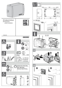
Surface mounted housing
134 31,5 108 130 27,5 193 82 DE Aufputz-Gehäuse DE Aufputz-Gehäuse EN Housing EN Housing for for surface installation surface installation x > 30 mm x 152296-00 152296-00 A B … 2 IP 40 a – … °C ... + 70°C c a ≤ 119 mm b b ≤ 93 mm c ≤ 55 mm DIN EN ISO 4762 M4x... DIN 7984 M4x... DIN ISO 7049 ST3,5x... ... 4x … 1 … 3 … 1 … 3 … A B … 2 … 4 … 5 … Nm … 1 click … click … click 134 134 24 108 click 24 … 4 … 3 … 2 click click … 5 … GEZE GmbH Reinhold-Vöster-Strasse 21–29 71229 Leonberg Germany Tel.: 0049 7152 203-0 Fax: 0049 7152 203-310 www.geze.com
(PDF | 5 MB)
Award certificate OL 95 fanlight opener with hand levers
VERLEIHUNGS-URKUNDE AWARD CERTIFICATE Nr./ No. 13-1/00 (Version 03) Der Güteausschuss der Gütegemeinschaft Schlösser und Beschläge e.V. verleiht aufgrund des vorliegenden Prüfberichtes gemäß RAL-GZ 607/12 dem Oberlichtbeschlag: Based upon the test report according to RAL-GZ 607/12 which has been released by the quality assurance commission of the quality assurance association of locks and hardware hereby awards the fanlight hardware: OL 95 Oberlichtöffner mit Handhebel OL 95 Fanlight opener with hand lever Fensterwerkstoff: Holz Window material: Wood Die Prüfergebnisse sind auf andere Fensterwerkstoffe übertragbar. The test results are transferable for other window materials der Firma: the company: GEZE GmbH Reinhold-Vöster-Str. 21-29 D-71229 Leonberg im Rahmen der Mitgliedschaft bei der Gütegemeinschaft Schlösser und Beschläge e.V., das von RAL (Deutsches Institut für Gütesicherung und Kennzeichnung e.V.) anerkannte Gütezeichen Schlösser und Beschläge mit der Inschrift „Oberlichtbeschläge“ as part of the membership of the Gütegemeinschaft Schlösser und Beschläge e.V., the RAL-quality label shown below, having been recognized by the German RAL Institute for Quality Assurance and labelling „Fanlight hardware” geprüft nach RAL-GZ 607/12, Ausgabe … certified according to RAL-GZ 607/12, version … Die Führung des Zeichens Nr. 13-1/00 setzt die Einhaltung und Überwachung nach dieser Güte- und Prüfbestimmung voraus. Grundlage ist der Prüfbericht Nr. 13-1/00, 13-1/ … und 13-1/ … des PIV. Permission of using this RAL quality label no. 13-1/00 is based on the surveillance and the quality- and testing instructions. The basis is test report no. 13-1/00, 13-1/ … and 13-1/ … by PIV. Diese Urkunde hat insgesamt … Seite und ersetzt die Urkunde 13-1/00 vom … .2017. This certificate has a total of … page and replaces the certificate 13-1/00 from … .2017. D-42551 Velbert, 10. Juli/ July 2024 Geschäftsführer Managing Director FB_07_13_02_20 Gütegemeinschaft Schlösser und Beschläge e.V. ∙ Offerstraße 12 ∙ D-42551 Velbert
(PDF | 351 KB)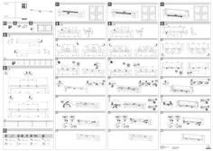
Slimchain installation instructions
Slimchain V1 V2 V3 … 1 … 2 … 2 … 3 148326-02 270 270 A B 300 500 www.geze.com 800 C D E G K L 194 500 260 560 196 498 294 600 360 660 296 598 444 750 510 810 446 748 … 2 … click … 1 … 3 … 6 … click … 5 … 4 click … 1 … 2 … click … 2 … 5 … 5 … ≥S1 ≥S2 ≥N2 300 1160 1200 300 500 1360 1420 350 800 1660 1870 425 4,8 x L ISO 7049 / DIN 7981 M5 x L ISO 7045 / DIN 7985 4,8 x L ISO 7049 / DIN 7981 4,5 x L DIN 7996 Ø 4,0 mm M5 x L (Form SK) Ø 4,0 mm Ø 3,0 mm … 2 … 1 … 2 … 3 … 3 GEZE GmbH Reinhold-Vöster-Strasse 21–29 71229 Leonberg Germany Tel.: 0049 7152 203-0 Fax: 0049 7152 203-310 www.geze.com … 3
(PDF | 4 MB)